


FIRE & SMOKE DAMPERS
(Certified 120 Minutes Fire Rating as per UL-555 S- 1995)
Application
Cosmic range of fire and smoke dampers are tested and certified for 120 mts fire rated as per UL-555 standards by CBRI Roorkee and they are designed to prevent the free passage of smoke and fire in the air distribution ducts in Air conditioning and ventilating systems. Fire dampers are available with or without extended sleeve models.Mounting
Fire damper without sleeve model are fixed for duct mounting and the extended sleeve fire dampers are suitable for wall mounting by means of bolts and nuts.Standard Consrtuction Details
Frames:1.6mm thick high quality galvanized steel frames having 150mm depth for without sleeve model and 165mm depth for with extended sleeve model fully welded and robust construction.Blades:: 1.6mm / 1.2mm thickness high quality galvanized steel heavy duty inter locking 'V' grooved blades having standard 150mm depth
Extended Sleevess: 1.6mm/1.2mm high quality galvanized steel sleeve with welded construction sleeve length available for 300mm to maximum 800mm long
Spindles and bearings: Ø 9.3x63mm chrome plated spindles with self lubricated Ø 14.5xØ 9.3 brass bushes for all of our fire and smoke dampers.
S.S Jamseals: Stainless steel gaskets are provided in the both sides to prevent spread of smoke and fire in the damper.
Implementation
Frame with flat frontal face and inner V grooved type multi blades assembly. Frames are welded and inner blase are connected to the frame by means of spindle rods and bushes. Bushes are available in brass or bronze. All biades are connected by a suitable flat link arrangement.The dampers are also provided with S.S Concealed jam seal (compression type) on the sides to prevent spread of smoke and fire.
Available in three model as follows fire dampers with shutting mechanism by thermal fusible link, Motorized fire dampers with spring return Actuator, Control panels and motorized fire damper with extended sleeve type especially for mounted on the walls. In this sleeve model the damper actuators and optional accessories are normally externally mounted on one side of the dampers sleeve, these items are kept on the right side of the sleeve normally.
(Right side mounting) as on request they may be kept on left hand side of the sleeve also (left side mounting)
FUSIBLE LINK AND SPRING MECHANISM :
The damper is held open by a UL 555 stamped fusible link and spring fixed with flat link arrangement if the temperature in the damper increased more the 74° C the fusible link will be shuttling close damper with spring action.Fire and Smoke damper with actuators mechanism, control panel and temperature sensor The damper is kept open by the actuator, signal received from the smoke detector fire panel or temperature sensor through the control panel. The actuator will close the damper. If the actuator is spring return model when the power is not available during smoke and fire condition the spring return actuator shall shut the damper.
CONTROL OPTIONS
Dampers are available with UL 555 - Fusible Link with spring mechanism or with electrical actuators operations.AVAILABLE SIZES
Sizes available from minimum 200x200mm to maximum in any standard or Non standard sizes.CONTROL PANEL FOR SMOKE AND FIRE DAMPERS
FEATURES
( a ) ACTUATION SYSTEM
Actuators ( spring return or non - spring return ) and soleniods of any make can be controlled from the control panel . Connections 1,2,3,4,5 Et 6 of in the control panel are used for the purpose . Please refer to DAMPER ACTUATOR Connections in the connections diagram for further details.
( b ) AIR HANDLING UNIT ( A.H.U) INTERLOCKINING
A.H.U. Fans can be easily put on or put off automatically with the help of control panel. Please refer to A.H.0 Connections in the connections diagram for further details.
( c) WARNING SIGNAL CONNECTIONS
A hooter / Alarm / flasher can be easily put on or put off automatically with the help of control panel . Please refer to ALARM Connections in the diagram for further details.
( d )EXTERNAL PANEL ( FIRE PANEL) CONNECTIONS
The control panel can be easily connected to any external panel (fire panel). A normally closed point (N/C) and a common point (com) of any operative relay on the external panel (fire panel) may used for this purpose. Note that these relay points should be at panel Zero potential. Please refer to EXT. Connection in the diagram for further details.
( e) HEAT DETECTOR CONNECTIONS
Heat detector is nothing but a thermal fuse . after reaching a particular temperature , this fuse blows off. the control panel senses the blowing off of the heat detector and puts off the A.H.U. fans , put on the warning signal and close the damper with help of an actuator / solenoid . Please refer to TEMP. Connections diagram for further details
.
( f ) SMOKE DETECTOR CONNECTIONS
Smoke detector, after sensing smoke , produce an alarm signal which is captured by the control panel automatically puts off the A.H.U. fans by breaking the power supply to A.H.0 . and also puts on the warning signal to actuator the supply to a hooter / alarm / flasher . The control panel also gives a closing signal to the actuator / solenoid which closes the damper. Please refer to smoke sense connections in the connection diagram for further details.
( g ) RESET BUTTON ( FOR MANUAL OPERATION )
The damper can be opened or closed with help of a PUSH BUTTON provided to the face of the control panel .
( h ) INDICATION
( 1 ) POWER INDICATION A red lamp indicates the presence of power supply.
( 2 ) DAMPER OPEN INDICATION Indicates the status of damper position i.e. open .A green lamp glows if the damper is open
(3 ) DAMPER CLOSED INDICATION Indicates the status of damper position i.e. closed . A yellow lamp glows if the damper is closed Please note status of damper position i.e. closed ( open / closed ) shall be available only if either AUX . Contacts of the actuator or micro switch contacts are connected to connections nos .4,5a6 in the control panel .
(4) Indicates warning immediately, once control panel receives a signal of smoke or fire or both . A red lamp glows for this purpose.
COMPATIBILITY
The control panel can be easily connected to the reputed actuator makes such as BELIMO , STAEFA ( SIEMENS) , JOVENTA , HONEYWELL etc
Solenoids of CULTER — HAMMER or any other make can be easily connected to the control panel.
ELECTRICAL PARAMETERS
(a ) Operating voltage = 24V
( b ) Power Consumption < 0.8 For non — spring return actuators, use connections nos. 1 , 2, 3, 4, 5, & 6. Damper status indications ( open / close) shall be available only if either AUX. Contacts or microswitch connections are done at points 4, 5 & 6.
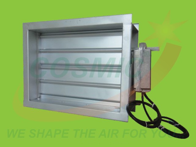 Fire Damper With Motor
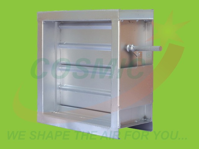 Fire Damper With Motor Fixing Rod
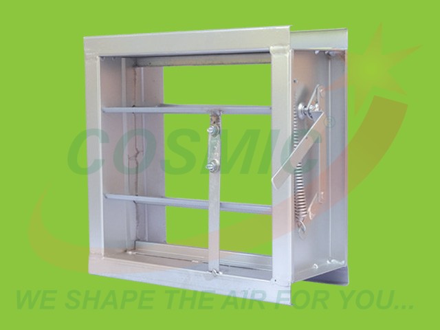 Fire Damper With Fusable Link
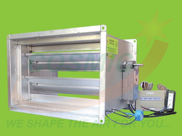 Fire damper With Sleeve(Certified 120 Minutes Fire Rating as per UL-555 S-1995)
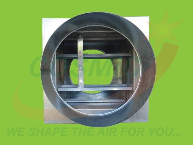 Fire Round Fire Damper


